Stryker Renaissance Parts Manual
. IMPORTANT File in your maintenance records Renaissance Series 1066 Head/Neck Surgery Bed MAINTENANCE MANUAL For Parts or Technical Assistance 1–800–327–0770. Table of Contents INTRODUCTION.SPECIFICATIONS. Table of Contents ASSEMBLY DRAWINGS AND PARTS LISTS (CONTINUED) Knee Gatch Crankscrew Assembly.Footsection Assembly.
Introduction INTRODUCTION This manual is designed to assist you with the operation and maintenance of the 1066 Head/Neck Surgery Bed. Read it thoroughly before using the equipment or beginning any maintenance on it. SPECIFICATIONS Maximum Weight Capacity 500 pounds Overall Bed Length/Width 88”, 31.5”. Preventative Maintenance CLEANING 1. Hand wash all surfaces of the bed with warm water and mild detergent. Dry thoroughly. Clean Velcro AFTER EACH USE.
Saturate Velcro with disinfectant and allow disinfectant to evaporate. (Appropriate disinfectant for nylon Velcro should be determined by the hospital.) BIANNUAL CHECKLIST All fasteners and knobs secure (reference all assembly prints) Siderails move and latch properly (page 5).
Service Information SIDERAIL LATCH ADJUSTMENT Required Tools: 1/8 Hex Allen Wrench WARNING The siderail latch adjustment is pre–set at the factory, and there should not normally be a need for readjust- ment. If adjustment must be done it is important to follow the procedure below. If it is not done properly, injury to the patient or user could occur. Service Information PEDAL LINKAGE ADJUSTMENT – DUAL SIDE CONTROL BASE Required Tools: 3/32 Hex Allen Wrench 7/16 Open End Wrench 1/2 Open End Wrench (2) Wooden blocks (10 – 12 inches in length) Adjustment Procedure: 1. Pump the litter up to full height.
Service Information PEDAL LINKAGE ADJUSTMENT – DUAL END CONTROL BASE Required Tools: 7/16 Open End Wrench 1/2 Open End Wrench (2) Wooden Blocks (10 – 12 inches in length) Adjustment Procedure: 1. Pump the litter up to full height. Lift the base hood, separating the hood from the base frame.
Using the wooden blocks, support the base hood. Service Information CASTER ASSEMBLY REPLACEMENT. Required Tools: 1/8 Roll Pin Punch Drill with 1/8 inch Drill Bit Flat Punch (any size larger than 1/8) Hammer Needle Nose Pliers Floor Jack 3/4 Inch Wrench (2) Wooden Blocks (10 – 12 inches in length) 1 Inch Wrench Torque Wrench (w/ Ft. Jack will not pump up and the jack actuator rod Remove excess air (vacuum) in system (see p. May or may not move. Contact Stryker technical service at 1–800–327–0770 for further assistance. The hydraulic fluid should be visible at the bottom of the fill hole.
His parents, originally from India, say they are proud to see his studying pay off, but winning the bee isn't the most important part of being an expert speller. “He's able to communicate much better in different situations, and it will be easier for him to read different books and understand things better when he has a wider vocabulary,” Gargi said. Dallas business journal.
If it is not, add Mobil Aero HFA hydraulic fluid (Stryker part number 2020–70–475) until the fluid is visible at the bottom of the fill hole. Replace the fill plug.
Service Information JACK DESCENT RATE ADJUSTMENT Required Tools: Screwdriver (2) Wooden Blocks (10 – 12 inches in length) Adjustment Procedure: 1. Pump the litter up to full height. Lift the base hood, separating the hood from the base frame. Using the wooden blocks, support the base hood. Service Information HYDRAULIC CHECK VALVE REPLACEMENT Required Tools: 3/8 Open End Wrench Stiff Wire (with bent, pointed end) Small Needle Nose Pliers 3/4 Open End Wrench Torque Wrench (with Ft. Adjust.) 7/32 Hex Allen Wrench 1/2 Inch Diameter Rod Replacement of Valve #1 WARNING To avoid personal injury or damage to the stretcher, remove the litter and the base hood before beginning.
Service Information HYDRAULIC CHECK VALVE REPLACEMENT (CONT’D) Replacement of Valve #2 WARNING To avoid personal injury or damage to the stretcher, remove the litter and the base hood before beginning service on the jacks. Lower the jack rod completely to relieve the pressure on the pump piston side of the jack. Service Information BRAKE ADJUSTMENT Required Tools: 3/32” Hex Allen Wrench Pry Bar Thread ”Locktite” BASE LUBRICATION Do not grease area shown. Lubricate brake adjuster rod around area shown with MPG–2 grease or equivalent. 1066–45–19 Side Control Base Assembly (with Wheels) Note: Parts and assemblies drawn with broken lines are optional accessories. 1066–45–19 Side Control Base Assembly (with Wheels) Item Part No. Part Name Qty.
715–1–245 Base Weldment Assembly 38–211 Spring 715–1–158 Caster Nut 715–1–61 Caster Brake Assembly (Page 18) Brake Adjuster Assembly 1066–1–34 Brake Rod Assembly 1000–10–62 Steering Lock Linkage Bar (Page 19) Brake Cam Assembly 715–1–94. 715–1–150 Brake Adjuster Assembly Item Part No. Part Name Qty. 715–1–62 Threaded Stud Assembly 14–4 Nylon Washer 715–1–180 Bearing 28–8 Retaining Ring. 715–1–213 Brake Cam Assembly Item Part No.
Part Name Qty. 715–1–221 Brake Cam 16–59 Fiberlock Nut 8–21 Soc. Cap Screw 715–1–173 Brake Connecting Link. Brake Pedal Assembly, Side Control Base Item Part No. Part Name Qty.
715–1–170 Brake Pedal Ass’y, Welded 715–1–145 Brake Pedal. 2020–46–220 Steering Caster Assembly Item Part No. Part Name Qty. 946–1–279 Caster Assembly 1000–59–10 Latch Ass’y, Steer Caster. Caster and Caster Cover Assembly Item Part No. Part Name Qty.
946–1–276 Caster Assembly 715–1–139 Caster Cover, Left 715–1–138 Caster Cover, Right 23–59 Pan Hd. Self–Tapping Screw. 715–1–25 Fifth Wheel Assembly Item Part No. Part Name Qty. 715–1–339 Fifth Wheel Pivot Assembly 715–1–17 Fifth Wheel Bushing 16–11 Flexlock Nut 715–1–15 Spring 715–1–13 Fifth Wheel Bracket 16–12 Flexlock Nut 390–1–54 Wheel 3–31 Hex Head Cap Screw 3–82 Hex Head Cap Screw. 716–1–251 End Control Base Assembly (with Wheels) Note: Parts and assemblies drawn with broken lines are part of optional accessories.
716–1–251 End Control Base Assembly (with Wheels) Item Part No. Part Name Qty.
Ford Parts Manual
716–1–246 Base Weldment Ass’y 8–17 Soc. Shoulder Bolt 715–1–158 Caster Nut 715–1–61 Caster Brake Assembly (Page 18) Brake Adjuster Assembly (Page 26) Brake Pedal Ass’y, Ft. End 8–21 Soc. 716–1–263 Brake Pedal Ass’y, Foot, End Control Base Item Part No. Part Name Qty.
716–1–275 Brake Pedal 716–1–262 Brake Rod Ass’y, Ft. 716–1–269 Brake Pedal Ass’y, Head, End Control Base Item Part No. Part Name Qty. 716–1–275 Brake Pedal 716–1–267 Brake Rod Ass’y, Welded. 715–1–260 Side Control Base Assembly (with Jacks).
715–1–260 Side Control Base Assembly (with Jacks) Item Part No. Part Name Qty.
29–7 Dual Lock (Page 38) Jack Assembly 715–1–55 Jack Base Mounting Plate 3–62 Hex Hd. Cap Screw 11–3 Flat Washer 16–36 Nylock Hex Nut 715–1–192 Jack Support 3–85 Hex Hd. 715–1–108 Pedal Base Assembly, Pump Item Part No. Part Name Qty. 715–1–83 Pedal Ass’y Weldm’t, Pump 715–1–126 Side Control Pedal Pad 81–44 Bearing, Bronze.
715–1–109 Pedal Base Assembly, Head End, Left Item Part No. Part Name Qty.
715–1–98 Release Ped. 721–40–25 Pedal. 715–1–110 Pedal Base Assembly, Head End, Right Item Part No.
Part Name Qty. 715–1–97 Release Pedal Weldment 721–40–25 Pedal. 715–1–135 Side Control Base Hood Assembly Item Part No. Part Name Qty. 715–1–153 Hood Spacer 715–1–151 Foam Hood Mount 715–1–176 Oxygen Bottle Retainer 11–16 Washer 25–88 Pop Rivet. 716–1–270 End Control Base Assembly (with Jacks).
716–1–270 End Control Base Assembly (with Jacks) Item Part No. Part Name Qty. 716–1–293 Rel Pedal, Hd. 716–1–294 Rel. (Page 36) Pump Pedal Ass’y, Foot 715–1–115 Pump Conn. Rod Ass’y (Page 36) Pump Pedal Ass’y, Head 14–3. 716–1–292 & 288 Pump Pedal Assembly, Head & Foot Item Part No.
Part Name Qty. 716–1–285 Pump Pivot, Head End 26–12 Roll Pin 716–1–290 Pump Ped. Wldmt., Head 721–40–25 Pedal Item Part No. Part Name Qty. 716–1–283 Pump Pivot, Foot End 26–12 Roll Pin 716–1–289. 716–1–99 End Control Base Hood Assembly Item Part No. Part Name Qty.
716–1–153 Hood Spacer 715–1–151 Foam Hood Mount 715–1–176 Oxygen Bottle Retainer 11–16 Washer 25–77 Pop Rivet. 715–1–310. Jack Assembly Item Part No. Part Name Qty.
Item Part No. Part Name Qty. 45–904 O–Ring 45–110 O–Ring 715–1–340 Cap Assembly 388–1–38 Plug 390–1–243 Gasket 715–1–322 Reservoir 715–1–323 Actuator Cylinder 390–1–244 Gasket 715–1–325 Actuator 390–1–238 Gasket, Actuator 45–14 O–Ring (Page 39) Jack Base Assembly 926–20–161. 715–1–300 Jack Base Assembly, Foot Control Item Part No. Part Name Qty.
Item Part No. Part Name Qty. 715–1–312 Base, Machined 45–110 O–Ring 715–1–308 Base Plug 715–1–328 Piston Wear Ring 715–1–306 14–50 Bearing Retainer 28–8 Snap Ring 715–1–327 Cylinder Wear Ring 390–2–176 Washer 715–1–316. Specification Label 1066–1–19 Brake/Steer Label, Head 1066–1–18 Brake/Steer Label, Foot 1066–1–23 Side Strip Label 1060–1–50 Renaissance Logo Label 946–1–60 Stryker Logo Label 741–34–18 “Head Point” Label, Left 741–34–19 “Head Point” Label, Right Item Part No. Part Name Qty. 1066–1–17 Specification Label 1060–1–50.
1066–1–10 Litter Assembly. 1066–1–10 Litter Assembly. 1066–1–10 Litter Assembly Item Part No. Part Name Qty.
Item Part No. Part Name Qty. 1066–1–50 Frame Assembly (page 46) Trans. 721–26–69 Upright Sleeve (page 47) Trans.
Cap Screw 38–218 Tension Spring 16–28 Nylock Hex Nut 10–11. 1066–1–90 Jack Support and Trend.
Limiter Assembly Item Part No. Part Name Qty.
1066–1–13 Hd. Jack Mount Ass’y, Rt. 1066–1–91 Hd. Jack Mount Ass’y, lt. 938–1–401 Collar 3–54 Hex Hd.
Cap Screw 46–1 Set Screw (page 45) Trend Limiter Assembly 721–32–160 Support Tube Assembly 16–28. 1010–23–34 Trend. Limiter Assembly Item Part No. Part Name Qty.
1010–23–35 Limiter Plate Ass’y 4–8 Hex Soc. Machine Screw 15–23 Hex Nut 4–142 Hex Soc. Machine Screw 715–1–114 Limiter Pin Assembly 38–233 Extension Spring 16–16 Fiberlock Nut.
1010–32–103 Short Transfer System Assembly, Left Item Part No. Part Name Qty. 1010–32–100 Transfer Board Ass’y 721–24–46 Label 1010–32–98 Pivot 1010–24–22 Connecting Link Ass’y 1010–32–94 Pivot Arm Ass’y, Left 28–93 Retaining Ring 3–50 Hex Hd. Cap Screw 11–224 Nylon Flat Washer 14–21 Nylon Flat Washer 4–156. 1010–32–104 Short Transfer System Assembly, Right Item Part No.
Part Name Qty. 1010–32–100 Transfer Board Ass’y 721–24–46 Label 1010–32–98 Pivot 1010–24–22 Connecting Link Ass’y 1010–32–96 Pivot Arm Ass’y, Right 28–93 Retaining Ring 3–50 Hex Head Cap Screw 11–224 Nylon Flat Washer 14–21 Nylon Flat Washer 4–156. 1010–24–30 Board Support Assembly Item Part No. Part Name Qty. 1010–24–15 Support Block 1010–24–16 Support Arm 1010–24–14 Warning Label 38–263 Spring 8–17 Shoulder Bolt 1010–26–46 Ball Knob. 1066–33–17 Crank Fowler Assembly Item Part No. Part Name Qty.
(page 50) Crank Fowler Subassembly 8–28 Shoulder Bolt 11–179 Washer 16–28 Lock Nut 8–15 Shoulder Bolt 14–3 Flat Washer (page 52) Crankscrew Assembly 3–79 Hex Hd. Cap Screw 3–73 Hex Hd. Cap Screw 1510–33–38 Crank Fowler Pivot 1010–34–15. 1066–33–7 Crank Fowler Subassembly BOTTOM VIEW. 1066–33–7 Crank Fowler Subassembly Item Part No. Part Name Qty. 1066–33–4 Fowler Skin 1066–33–61 Head Piece Skin 1066–33–20 Crank Fowler Weldment 25–103 Pop Rivet 1066–33–69 Pivot 11–1 Washer 25–50 Pop Rivet 1066–33–63 Bellows 1066–33–50 Cover 1066–33–60 Right Angle Gear Drive 1010–32–66 End Plug 1066–75–21.
1066–33–19 Fowler Crankscrew Assembly Item Part No. Part Name Qty. 14–55 Nylon Washer 1510–34–85 Crank Assembly 946–23–18 Crank Disc 938–1–177 Knob 16–5 Conelock Nut 378–24–29 Shoulder Bolt 946–33–35 Fowler Screw 26–14 Roll Pin 81–174 Thrust Washer 938–1–175 Bearing Assembly 81–176 Thrust Washer 81–175 Thrust Bearing. 1066–34–70 Knee Gatch Assembly Item Part No. Part Name Qty. (page 54) Midsection Preassembly (page 54) Foot & Thigh Preassembly 16–28 Nylock Hex Nut 1010–32–60 Pivot Bolt 3–73 Hex Hd. Cap Screw 11–179 Washer 4–105 Soc.
Cap Screw 16–12 Flexlock Nut 25–79 Pop Rivet. 1066–34–39 & 1066–34–57 Knee Gatch Preassemblies Item Part No. Part Name Qty. 1010–34–25 Thigh Section Assembly 1066–34–59 Thigh Section Skin 1066–34–26 Foot Section Assembly 1010–32–60 Pivot Bolt 16–28 Nylock Hex Nut 1066–34–63 Calf Section Skin 25–103 Pop Rivet 11–179 Washer 1010–34–23 Calf Stand Bar 25–79.
1066–34–13 Knee Gatch Crankscrew Assembly Item Part No. Part Name Qty. 946–33–18 Crank Disc 1510–34–85 Crank Assembly 26–45 Roll Pin 26–14 Roll Pin 81–176 Thrust Washer 81–175 Thrust Bearing 81–174 Thrust Washer 938–1–175 Bearing Assembly 938–1–177 Knob 378–24–29 Shoulder Bolt 16–5 Conelock Nut 946–34–25. 1066–1–37 Foot Section Assembly Item Part No. Part Name Qty. 1066–1–39 Foot Section Weldment 1066–32–105 Foot Section Skin 25–103 Pop Rivet 7900–1–102 Velcro Pile Tape 24 1/2” 16–28 Nylock Nut 3–73 Hex Hd. Cap Screw 721–31–65 Hole Plug.
1066–1–60 Handle Assembly Item Part No. Part Name Qty. 1066–1–61 Handle Weldment 37–2 Hole Plug.
1066–70–25 Wrist Rest Assembly Item Part No. Part Name Qty. (page 59) Upright Assembly 1066–70–33 Vertical Assembly 16–28 Lock Nut 3–50 Hex Hd. Cap Screw (page 60) Knob Assembly. 1066–70–22 Upright Assembly Item Part No.
Part Name Qty. 1066–70–13 Tube Assembly 17–4 Acorn Nut 38–171 Compression Spring 966–51–19 Wedge Lock, Modified 11–108 Washer 966–51–18 Shaft 966–51–24 Knob Assembly, Modified 4–66 Soc. Cap Screw 1066–70–17 Support Assembly 966–1–65 Label 4–97 But. 1066–70–24 Knob Assembly Item Part No. Part Name Qty. 1066–70–34 Extension Tube Assembly 24–11 Knob 26–7 Roll Pin. Pre–Op/Post–Op Head Addition Assembly 1066–75–11 (3”) 1066–77–23 (4”) Item Part No.
Part Name Qty. Item Part No. Part Name Qty. 1066–75–20 Specification Label 1066–77–10 Specification Label 1066–75–19 Frame Weldment 1066–75–19 Frame Weldment 1066–75–21 Weight Label 1066–75–21 Weight Label 1066–75–12 Arm Pad Assembly, Lt. 1066–77–20 Arm Pad Assembly, Lt.
1066–82–19 Inflatable Air System Head Pad Item Part No. Part Name Qty. 1066–82–20 Latex Bulb 1066–82–9 Cover Assembly 1–10 Flat Head Screw 1066–82–16 Air Conduit Assembly 1066–82–13 Bottom Foam 1066–82–14 Bladder 1066–82–21 Connector 1066–82–12 Top Foam 1066–82–22 “T” Connector 1066–82–15 Head Piece Base. 1066–85–10 Sheet Support Assembly Item Part No. Part Name Qty. 1066–85–20 Specification Label 1066––85–13 Goose Neck 1066–85–15 Insert Assembly 1066–85–24 Directional Retainer, Bottom 1066–85–23 Directional Retainer, Top 1066–85–22 Linear Retainer, Bottom 1066–85–21 Linear Retainer, Top 4–167 Screw. 1066–26–15 & 1066–26–17 Siderail Ass’y, Right & Left HEAD END Item Part No.
Part Name Qty. 1010–26–15 Top Rail 1010–26–34 Upright 1010–26–36 Upright, Bent 1010–26–66 Sleeve Bearing 25–106 Semi–Tubular Rivet 721–26–84 Round Hole Plug 1066–26–25 Latch Upright 1010–26–12 Bent Spindle Rest. 1066–87–16 Drainage Pan Assembly Item Part No. Part Name Qty.
1066–87–15 Drainage Pan 1066–87–20 Specification Label 4–169 Button Hd. Cap Screw 1066–87–17 Drainage Support. 1010–59–10 Permanent I.V.
Pole Assembly Item Part No. Part Name Qty. 1010–59–24 Base Tube Ass’y 1010–59–30 Exten. Tube Ass’y 1001–59–47 Lock Ring 1001–59–46 Lock Actuator 14–20 Nylon Flat Washer As Req’d 1010–59–16 I.V.
Hook 52–17 Nylon Spacer 7–4 Truss Hd. 1010–80 Permanent I.V. Pole Mounting Assembly Item Part No. Part Name Qty.
(Page 66) I.V. Pole Ass’y 1001–259–11 I V. Socket Ass’y 4–91 But. Cap Screw 16–20 Self–Locking Nut 1001–59–42 I.V. 1010–80–100 Replacement Permanent I.V. Pole Ass’y Item Part No.
Part Name Qty. 16–20 Self–Locking Nut (Page 66) I.V. Pole Ass’y 1001–259–11 Socket Ass’y 4–91 But. Cap Screw 16–28 Nylock Hex Nut 4–161 Button Hd.
Cap Screw 1001–59–42 I.V. 741–34. Footboard/Chartholder & 1010–30 Bottle Holder Ass’y Item Part No. Part Name Qty. 946–28–11 Chart Holder 741–29–18 Head/Foot Board.Replacement Part Number 741–34–100 Item Part No. Part Name Qty.
1010–30–11 Upright Bottle Holder 27–12 Cotter Pin 741–30–24 Nylon Stand–Off 1010–30–17 Spec. 741–48–14 Defibrillator Tray Assembly Item Part No. Part Name Qty.
Item Part No. Part Name Qty.
946–39–4 Tray 741–48–12 Label 926–39–16 Crosstube 390–57–12 Long Strap 25–55 Rivet 390–57–13 Short Strap 926–39–9 Cover 946–1–283 Label 18–6 Umbrella Nut 741–48–20 Holder 29–8 Dual Lock 2–44 Screw. 1010–50–10 Foot Extension/Defibrillator Tray Ass’y. If requested by Stryker, products or parts for which a warranty claim is made shall be returned prepaid to Stryker’s factory.
Any improper use or any alteration or repair by others in such manner as in Stryker’s judgement affects the product materially and adversely shall. Claim will be limited in amount to the actual replacement cost.
In the event that this information is not received by Stryker within the fifteen (15) day period following the delivery of the merchandise, or the damage was not noted on the delivery receipt at the time of receipt, the customer will be responsible for payment of the original invoice in full. 6300 Sprinkle Road, Kalamazoo, MI (800) 327–0770 DH 5/92 1066–32–34 REV A.
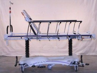
The Stryker Renaissance Stretcher includes a new mattress (.IV pole not included). It is certified to proper operating specifications and in excellent condition. Warranty: 1 Year - Parts and Labor. The Renaissance Stretcher is a full-featured, durable patient handling system that comes standard with Fifth Wheel Steering, increasing mobility while decreasing the amount of effort needed to push the stretcher. Pop-up handles allow for easy maneuverability and steel-ring brakes ensure that the stretcher remains a firmly locked working surface when needed. The Renaissance Stretcher is suited to be used for ambulatory surgery, emergency, surgery, recovery unit, maternity, PACU, cath lab, extended stay, endoscopy, ultrasound, trauma, cardiology, GI lab, nuclear medicine, radiology, transport, or outpatient surgery.
Stryker Renaissance Stretcher Features. 8' (20 cm) Omni Surface casters with wheel covers. Dual cylinder pneumatic backrest. Dual pedestal hydraulics. Uni-lower pedal. Fibersin backrest/steel foot-end litter. Retractable fifth-wheel steering.
Fold-down siderails (Models 1210 and 1710 only). Glideaway Siderails (Models 1231 and 1731 only). Four corner IV receptacles. Four-wheel steel-ring brakes with dual end activators.
Hands-free Trendelenburg. Integrated patient transfer boards. Integrated storage tray with oxygen bottle holder. Locking caster steering.
Pop-up push handles. Power-washable (Models 1231 and 1731 only). Rubber bumpers. Three-sided foot control hydraulics. Stryker Renaissance Stretcher Specifications.
Overall Length: 84' (213 cm). Overall Width:. #1210:. Siderails Up: 31.5' (80 cm). Siderails Down: 31.5' (80 cm). #1231:.
Siderails Up: 31.5' (80 cm). Siderails Down: 30' (76 cm). #1710:. Siderails Up: 34.5' (88 cm). Siderails Down: 34.5' (88 cm). #1731:.
Franchi Renaissance Parts Manual
Siderails Up: 34.5' (88 cm). Siderails Down: 30.5' (78 cm).
Weight Capacity: 500 lbs (228 kg). Height Range (to litter top):.
High: 35.5' (90 cm). Low: 22' (56 cm). Litter Positioning:. Backrest: 0 - 90°.
Knee Gatch: 0 - 30°. Trend./Reverse Trend.: ± 18°.
Patient Surface:. #1210 and #1231: 26' x 76' (66 cm x 193 cm).
#1710 and #1731: 29' x 76' (74 cm x 193 cm). Transfer System: 8' x 42' (20 cm x 107 cm). Siderails:. #1210 and #1710: 13' x 55' (33 cm x 140 cm). #1231 and #1731: 14' x 54' (36 cm x 137 cm).
Caster Diameter: 8' (20 cm). MFI makes ordering easy with simple shipping options. We select the best carrier depending on the specific product. Carriers range from FedEx, UPS, DHL, Freight, and more. We are experts at meeting deadlines. Our team of product specialists are available to quote expedited shipping and deliver within your deadline.
Call or email with any questions: Phone: Email: This table details available shipping methods, with respective transit times and costs: Order Value Destination Service Cost Transit Time $0-$199.99 Continental U.S. Standard $10.00 5-7 Business Days $200+ Continental U.S. Standard Free 5-7 Business Days $200+ Continental U.S. Freight (Loading Dock) Free 5-7 Business Days $200+ Continental U.S. Freight (Curbside) $45.00 5-7 Business Days $200+ Continental U.S.
White Glove Delivery (Residential) $500.00 7-21 Business Days $0-$199.99 Non-Continental U.S. Standard $45.00+ 7-14 Business Days $200+ Non-Continental U.S. Standard $35.00+ 7-14 Business Days $200+ Non-Continental U.S. Freight/White Glove Quoted TBD Any U.S. Expedited Quote TBD $0-$499 International TBD Customer Account Only TBD $500+ International TBD Quote TBD Standard Shipping Rules: Shipping within Continental U.S.
Free shipping on orders of $200 or more. $10 shipping charge on orders under $200 Freight Shipping. Free Dock to Dock Shipping on orders traveling within the continental U.S. $45 charge for liftgate curbside delivery. Order will arrive secured to a pallet. Customer is responsible for unpacking and disposing of packing material.
White Glove Delivery. White Glove Delivery means that the Carrier Delivery Agents will unload and place your items in the room of your choice. White Glove service includes unpacking, removal and disposal of packing materials. Customer is responsible for ensuring that the items can be delivered in the desired room without issue. Carrier Delivery Agents are not able to remove old equipment or obstacles.
$300 White Glove Delivery charge per order to commercial locations. $500 White Glove Delivery charge per order to residential locations. Expedited Shipping. Expedited shipping is available for an additional charge. If you're facing a time constraint, please select an expedited shipping option during checkout. Our specialists will contact you via phone or email with the expedited shipping cost and options prior to processing your order. Additionally, MFI is able to ship using the customer's shipping account if requested.
Shipping Outside Continental U.S. Orders of $200 or more have a shipping charge of $35 applied through our website. Orders under $200 have a shipping charge of $45 applied through our website.
Our processing team may contact you with an additional shipping cost prior to processing your order. Feel free to email or call to get exact shipping costs. Freight and White Glove Delivery, Outside Continental U.S. Freight and White Glove Delivery is available for an additional charge for addresses outside the continental US. Please select the Freight or White Glove Delivery option during checkout. Our specialists will contact you via phone or email with the additional delivery cost prior to processing your order. Feel free to email or call to get exact shipping costs.
Shipping Internationally. Please note that the international shipping cost does not include additional taxes and fees that may be applied by customs.
Recipient is responsible for covering any costs incurred through customs as well as providing required documentation for the shipment to be successfully delivered. If the recipient does not follow through with required documentation and/or taxes and fees, the order is subject to cancellation, and all shipping costs incurred will be deducted from the refund in addition to the standard return fees. MFI will not be providing shipping quotes for orders under $500.
Customers will need to use their own shipping account, or the order can be sent to a freight forwarder within the U.S. Where the customer will be responsible for getting their items to their destination. Other Considerations Damaged Shipments:. Please thoroughly inspect your package upon delivery.
Customer must notify the carrier of any visible damage at time of delivery for insurance claim purposes. Non-visible damage to the product due to shipping must be reported to MFI within 48 hours from the time of delivery. If the equipment is damaged beyond use or visibly needs repair, the customer should refuse delivery of the shipment and notify MFI immediately. Return Policy:. No merchandise may be returned without prior written authorization by MFI. Customer is responsible for all shipping expenses. A 20% restocking fee is applied to all approved returns.
Restocking fee is waived for exchanges and store credit. Returns must be requested within 30 days from the date of delivery. Authorized returns must be returned within 5 business days of the return authorization. We recommend submitting the tracking number via email. MFI shall test returned products and may impose a customer fee if the customer misrepresents the condition of the product or the item is damaged during shipping. New products need to be in original packaging.
Some products sold by MFI are non-returnable. Please check product listings for more information. MFI has the right to deny any request that does not coincide with the guidelines provided. Credit Guidelines. MFI Error: 100% credit including shipping expenses. Unused goods in original packaging receive an 80% credit, and customer is responsible for shipping expenses both ways.
Damaged goods will receive credit dependent on the condition of the product, and customer is responsible for shipping expenses. No credit will be issued if the item is non-returnable, such as a custom or special order, or in the case that the item is damaged due to improper handling/packaging by the customer. Return & Cancellation Questions How do I cancel my order? You may cancel your order by contacting us at or by giving us a call at (800) 633-1558.
There is no penalty for cancellation of an order prior to shipment, however, this does not apply to special/custom orders. What can I return? You may return most new, unopened items purchased within 30 days of delivery for a partial refund.
What is MFI Medical's return policy? The return period for returnable products is 30 days from date of delivery. No merchandise may be returned without prior written authorization by MFI.
Email for further information or request for return. When will I get my refund?
Typically, returns are processed in approximately 2-3 weeks. Most refunds are fully refunded in 3-5 days after we receive and process your return. What is the cost for returns? Please email for further information or request for return to determine cost of returns.